
This is a personal log as I design and build a virtual pinball cabinet. Not only will it play pinball, the front of the cabinet will have USB ports for other peripherals like game controllers, keyboards, mice, headphones, etc. to allow you to play virtually any game you wish on the 29″ translite. For instance, I have installed NES and SNES emulators if pinball isn’t your thing. Or, if you want to go modern, I have Steam installed with more than fifty different games, including every Valve game ever made, plus Borderlands, CoD, the Batman franchise and more.
Also, to make this a true game room centerpiece, I’ve incorporated Winamp and Pandora to make this a one of a kind jukebox. All remotely controlled with a Samsung tablet. For a touch of flair, Winamp is configured to play the visualization on the playfield while showing artist information and audio settings on the translite.
And, to really take this over the top, I’ve installed XBMC (also remotely controlled via tablet) to make this beast a full media center that can play Blu Ray, DVD, and all video files accessible through a wireless server.
To follow is a photo journal of how it was done.
THE CABINET ARRIVES
The Space Shuttle cabinet arrived home safe and sound. Don’t worry, it was not a restorable table, but the cabinet is in great shape.
Here are a couple shots to show the general condition of the cab before starting.


The original translite is a mess and absolutely useless.

The cabinet was brought in from the below zero temps on the back porch to the warm dining room.

My first set of pinball keys!

DISASSEMBLY
I started by gutting the head. This is when I learned how well assembled these cabinets are.


Some additional disassembly and rough cleaning of stainless steel trim. More on this toward the end of the project.


Then it was time to start gutting the cabinet


At first I was thinking about using some of the existing wiring and switches in my retrofit, but then realized it’s a LOT easier to scratch install those components.

LEFTOVERS.

The gutted, cleaned and assembled Williams standard body pinball cabinet. I left the legs off for ease of access and moving. A brand new set of legs is coming soon.

Who is this lucky bastard?


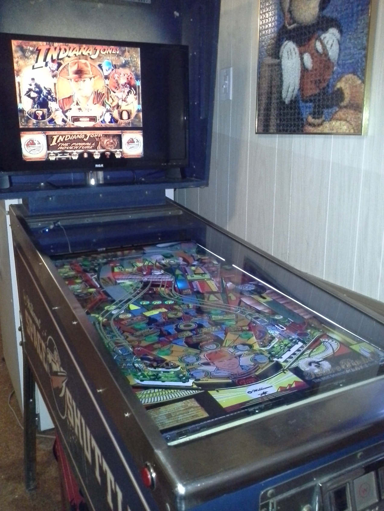
PLAYFIELD MONITOR
The 39″ TV for the playfield arrived from Sears. Cost was $249. Here I’m using a 21″ monitor for the translite, soon to be replaced by a nice, big 29″ LCD TV.


Below you can see the TV is larger than the opening in the cabinet. I was already aware of this and prepared to do what was necessary…

…I promptly decased it so it would fit inside the confines of the cabinet.

The very special, custom tool used to decase the TV, a George Foreman grill spatula!


First lesson learned: Once the screen is decased, DO NOT allow it to flex! Fortunately, I was able to return it for a replacement.

I received a new TV, but THIS time I used a glued wood frame attached to the TV with double stick tape to help support it inside the cabinet.


A perfect fit the first time, thanks to a TON of research and planning.

THE CPU
If the cabinet is the chassis, the PC is the engine. I’m using my gaming rig to run this beast. It’s far more than capable of doing it.
One thing that will set my pinball cab apart from the others is my choice to connect the PC externally to the cabinet. This eliminates the need for air circulation in the cab, as the only nominal heat produced is by the two LCD TVs. Another asset is that anyone can plug their own computer into the cabinet using the supplied 6′ umbilical harness. You can see the harness later in this post.
The CPU boasts a Pentium I7 Sandy Bridge processor and Nvidia 560ti GPU.

BUTTONS
To setup the buttons and learn the basics of button wiring, I created a fully working setup inside a cardboard box. I then plugged the cardboard box into my USB drive and viola, a fully functioning set of pinball buttons!


Here you can see that the Button Box works with any computer, such as this laptop. It gave me an idea for a future project of a completely portable pinball machine.

Next came the undoable act of drilling the cabinet (plan, plan, plan!), and mounting the buttons.


I’m not fretting over the chips in the wood from drilling. That all gets fixed with wood putty during the cabinet refinishing stage.

The buttons were then wired into the IPac using 16 gauge speaker wire. 100′ of speaker wire yields 200′ of 16 gauge, high quality insulated wire at about a third of the cost.

CABINET FLOOR
Then it was time for the cabinet floor. I used 1/8″ hardboard

Making the hole and mounting the crappy little subwoofer.
NOTE: I plan to eventually replace the subwoofer with an 8″ car audio speaker and move it toward the middle of the cabinet so I can install a small storage area behind the locking door. There I’ll keep remotes and gaming peripherals.


VOLUME CONTROL KNOB
This is a disassembled volume control for the speakers. I needed access to the potentiometer for what I did next.

I epoxied a brass tube to the potentiometer…

…and fed the brass tube through the plunger bracket..

…creating an analog knob by which I can control the master volume. Here you can see I haven’t attached the plunger knob yet, but when its done my volume control will look exactly like a traditional plunger.

POWER
Then it was time to install the main power switch and surge protector.
The surge protector is an industrial strength beast that I pulled from an old Kinkos digital photo kiosk. On the retail market, similar models sell for hundreds of dollars. I was lucky to find a free one!

on the underside of this junction box is a rocker on/off master power switch. It’s accessible through a hole in the cabinet floor.

WIRE HARNESS
Then came the wire harness construction using black, plastic wire loom. It really dresses the interior up nicely.


The 29″ translite monitor is purchased and installed. It’s an RCA that I picked up at Best Buy for $169.

PASS THROUGH PANEL AND OUTLET
The next step was the installation of the pass through panel. A pass through panel is required when you want to use an externally connected PC. This allows you to disconnect and use the PC in other areas of the house when not playing pinball.
A keystone pass-through plate and keystone pass-throughs for (2) HDMI, (2) USB, (1) 3.5 audio, and (1) VGA were assembled. Then the hole was measured, drilled and cut out with a jig saw.


The pass-through plate was installed.


Inside view

Then I cut a similar hole and wired an electrical outlet that simply plugs into the surge protector inside the cabinet. Now I had a single cord to power everything, even the PC.


I then created a 6′ umbilical harness to keep things nice and neat.

HEAD BEZEL AND SPEAKERS
Did you know that computer speakers and car speakers are practically the same? They both require 4 ohms of resistance, house speakers require 8 ohms to operate.
I purchased a set of JVC 5.25″ round speakers with a low (very low) RMS of 27 W (to match my cheap Logitech amplifier) and a max output of 220 W. More than enough for a jukebox in a medium sized noisy room.

I cut a panel of hardboard to fit the head. and cut out a window the exact size and location of the translite.


Then I taped the speaker grills to the bezel to work out the correct placement, removed the bezel and traced the grills on it. Make sure you have the bezel inserted in the head correctly or else your speaker placement will be centered incorrectly.


Using the template provided with the speakers, I traced a correct hole guide and screw template onto the bezel. Then cut out the holes with a fine tooth jig saw and mounted the speaker grills.


My bezel looks so happy! 🙂


Now, because the speakers attached to the bezel would make the bezel virtually unremovable, I opted to mount the speakers on a separate, permanently mounted board that sits behind the bezel.
Here I should mention; I was concerned about the powerful speaker magnets interfering with the screen so I spent a good part of a day researching ways to shield the translite, only to discover that speakers have no effect on LCD TVs. Only CRT monitors are affected by magnets, and then only the older ones. I had nothing to worry about. Let the install commence!


Here’s a shot of the fully assembled backbox with bezel in front.

And a detail shot showing how everything lines up when in place.

The fully assembled head with wired speaker panel. At first, the speakers sounded terrible! This was because all the audio settings on the PC are maxed out by default and this caused distortion. Once I set the PC’s master volume at around 70% things calmed down and I was able to get a much richer tone out of the speakers. There’s a bit too much treble for my liking when playing pinball. I hope to aleviate this when I install a proper subwoofer. When used as a jukebox, I simply use the Winamp equalizer to adjust properly. I wish there was an equalizer function for PinballX.

So far I’ve spent $1000 out of pocket (does not include CPU) and 70 days of working in my spare time.
LIGHT SHOW
I ordered a 16′ length of RGB LEDs and a Tao Tronics music controller. This causes the LEDs to flash to the beat of the music or pinball game and change colors.
It was a bit of a mess to get working. First, the controller didn’t come with a power supply nor any information as to what size power supply to use other than 12 V. Great, what’s the output recommendation? Thanks to Amazon reviews I got an answer and bought a 1.5 A output supply. Of course, the connector was wrong so it had to be hard wired into the controller. Long story short, I had a fifty/fifty chance at getting the poles correct. I plugged it in and the strip lit blue (perfect!), but when I tried the remote, nothing worked. I meticulously tried everything to fix the issue but no luck. Then, when I had nothing to lose since I had to send the unit back, I reversed the polarity on the power supply wires and BINGO!, everything worked…for a while.
I placed everything on the cabinet for a loose run. damn! the sound receiver quit working! Everything else worked though. I unplugged the unit and tried a tabletop test. Nothing worked, it didn’t even light up now.What the hell?!? Disassembling the unit, I discovered the ground wire had disconnected from the sensitivity control pot. I now need to repair it.
The disassembled controller waiting for me to solder the ground wire .

Update:
Saturday, with the help of a hobby vise, I soldered the ground wire back on the controller. I tested the system and everything works!
Sunday I mounted the controller into the cabinet and attached the LEDs to the back playfield and around the outer cabinet floor. A test showed everything to be working perfectly!!

Here’s a video of the jukebox and light show: https://www.youtube.com/watch?v=zW8U5VAxLGI
A vid of the War of the Worlds table: https://www.youtube.com/watch?v=oLLkAHIGgxg
And a vid of Gorgar, the world’s greatest pinball table!: https://www.youtube.com/watch?v=goXO5HFcFME
LEGS
I received the new chrome legs from Virtuapin. They are solid, sleek, and sexy!
To slide the cab across a carpeted floor, I bought 4 plastic, light switch covers. They work as good as any of those furniture glides and only cost .29 cent each.
PLAYFIELD BEZEL AND PAINT
The weather was warm enough to fabricate the playfield bezel and paint it along with the head bezel. The final step is to install the edge trim around the bezel window cut outs. I found the perfect u-channel trim at home depot for $2.50 for an 8′ piece. It’s located in the wood trim area. The playfield trim is perfect because, not only will it clean up the roughed edges and corners, it is also designed to fill the gap between the bezel and the screen where white light is can be seen. The trim is white and once it’s cut to fit, it will be painted black or maybe chrome!


And what pincab isn’t complete without a cup holder?

COMING SOON: PLAYFIELD LED COVER
One of the last pieces that still needs to be fabricated is the small cover/diffuser for the LEDs at the back of the playfield. This will be a simple piece of clear polycarbonate with dark window tint. The tint will diffuse the LEDs and hide the rear playfield area, while allowing the remote’s IR to still operate the LED controller.
The area to be hidden with the LED cover
CABINET GRAPHICS
Some of the most beautiful lines belong to the 1958 Corvette. Specifically the design of the car’s side cove.
It’s what has inspired my cabinet art. Below you can see the progression of my cab art as I lovingly borrowed the look of the 1958 Corvette.


…and an alternate design:

The proposed cabinet design. Next step is to order and apply the digital print vinyl.

